White paper
| Francois Gagnon
Daniel Tremblay Renaud Lavoie |
March 26, 2018
INTRODUCTION
This document explains a testing methodology on a wide receiver, defined in the SMPTE ST2110-21 specification. The specification describes and defines the traffic shaping of uncompressed video. In other words, it defines how the uncompressed video sender should send video packets over the network. Although it might sound obvious, we should state upfront that there are two different sender types. The narrow type is an isochronous type of sender. It is predictable (usually a hardware-dedicated engine is responsible for sending the packet) and will send packets at a constant pace. The second type is the wide sender. This type of sender will send packets in order but not in a predictable manner. The following figure (Figure 1.) shows the two types of senders.
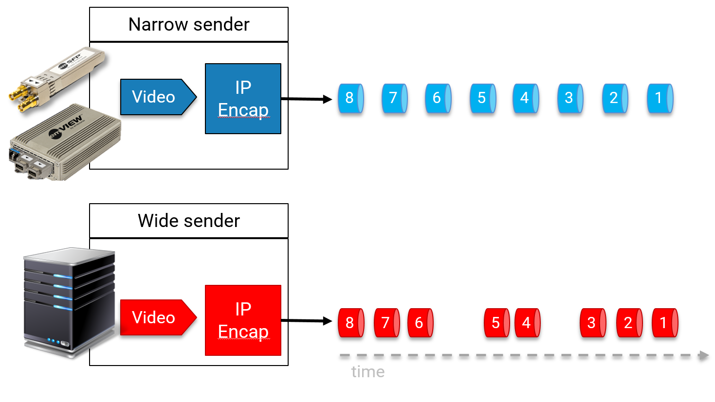
Figure 1. Narrow vs Wide Sender
We will consider here a network where the switches can buffer packets, add delays, and send out the packets in a wide sender manner. During the various installations we carried out ourselves, we did not see this behavior, but because Embrionix IP products are based on ST2110-21, any impact created by the network will be accepted.
A live network will always have some challenges. Packets will be lost on the way, or delayed, fragmented, arrive in the wrong order or become corrupted. The line may be completely down at times. Also, there may be times with bursts of traffic or network overload. In order to create these live network conditions to test robustness, we carry out IP impairment.
In addition to the above-mentioned challenges, the ST2110-21 sender can be a linear sender or gapped. So, what is a gapped and a linear sender? The term gapped defines a sender which usually takes an SDI or HDMI signal with blanking. During blanking, the sender can stop sending the packets (gapped) or can spread the packets in a linear manner (linear). The following figure (Figure 1.) shows a gapped vs a linear sender.
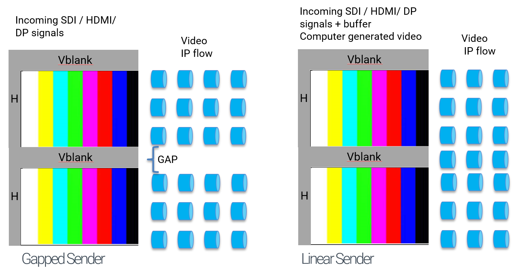
Figure 2. Gapped vs Linear Sender (example with Narrow Sender)
For simplicity’s sake, we will assume that narrow and wide senders can be both types: gapped and linear. Let's now see how we tested our ST2110-21 products against the wide transmitter. Many of our customers have asked us how we will guarantee that wide receiver will work. We will explore this here.
DEFINITION
To start with, let's define the different types of senders and receivers:
1.1 NARROW SENDER
A Narrow Sender is an isochronous type of sender. It is predictable and sends packets at a fixed interval, usually around 7 usec from packet to packet (for HD signals). The behavior is like USB packets transmission. In summary, it is a sender that sends packets at a fixed pace with a fixed spacing between them.
1.2 WIDE SENDER
A wide sender will send packets in order but not in a predictable manner. The packets can have large gaps between them, they can be grouped together, and can be bursty. In fact, the wide sender needs to be PTP- aware and needs to respect the frame rate. It may seem like this scenario is too chaotic, however ST2110-21 established some boundaries to ensure that this can all work. In particular, ST2110-21 ensures that the gaps between packets are manageable and don't add massive delays that would be unacceptable in a production environment. Again, for this reason, ST2110-21 established some boundaries, such as a buffer minimum of 720 packets, which is recommended in the wide receiver. This is a recommendation as a minimal packets buffer. For this reason, Embrionix IP products are equipped with configurable buffer size ̶̶ from a few packets, up to 4096 packets of buffer for HD, and Full HD streams. UHD buffer size is the size of one UHD frame.
1.3 DELAY
There are multiple blocks that create delay in a network, such as serialization delay, propagation delay and queuing delay in network devices (sources or switches). As we already well know, in video, delay can be troublesome for real-time applications. Delay is also present when the network includes low-speed links. To properly assess the delay experience, test equipment has been created. We will discuss in more detail how this equipment is used later in this paper.
1.4 IMPAIRMENT
As with delay, impairment at the physical layer is another stress that needs to be evaluated when rolling out a new network, application or technology. When bit level causes packet corruption or leads to a packet dropped by the switches, the video receiver should be able to cope with these problems. If we use a TCP-based application, the retransmission will slow down application throughput. In a UDP-based system when there is loss of integrity, the most obvious effect is loss of video, audio or metadata. To remedy the impairment, we used ST2022-7 in combination with ST2110 to ensure we always have a path of valid data.
1.5 NARROW RECEIVER
Narrow receiver is the receiver with limited buffer size and should be used in combination with narrow sender, otherwise no video will be readable after the IP transport. Narrow receivers are useful in a production environment, but our approach is to enable the customer to configure our core receiver to become a narrow or wide receiver with an extremely deep buffer ̶ up to 15 ms of buffer per input or output (for HD signal), depending on the application and environment.
1.6 WIDE RECEIVER
Wide receiver is the receiver that works with wide and narrow sender (transmitter). It has the buffer to handle the isochronous sender and the not-timed (non-isochronous) sender. As mentioned earlier, to avoid extra delay when used in a production environment, the Embrionix wide receiver has a configurable buffer depth.
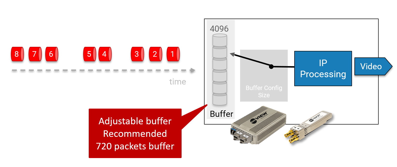
Figure 3. Wide Receiver with Configurable Buffer Size
1.7 EMBRIONIX CORE RECEIVER
The Embrionix IP core receiver used in all our emVIEW, emSFP and emMODULAR solutions is built with a large buffer of 4096 packets and more (up to 15 msec of buffer) per channel. The following image shows the emVIEW with dual HDMI output and with quad SDI with 4096 packets buffer per channel.
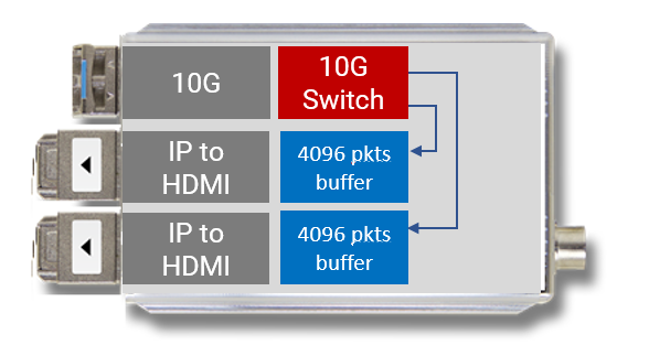
Figure 4. emVIEW-DMI-2 Details
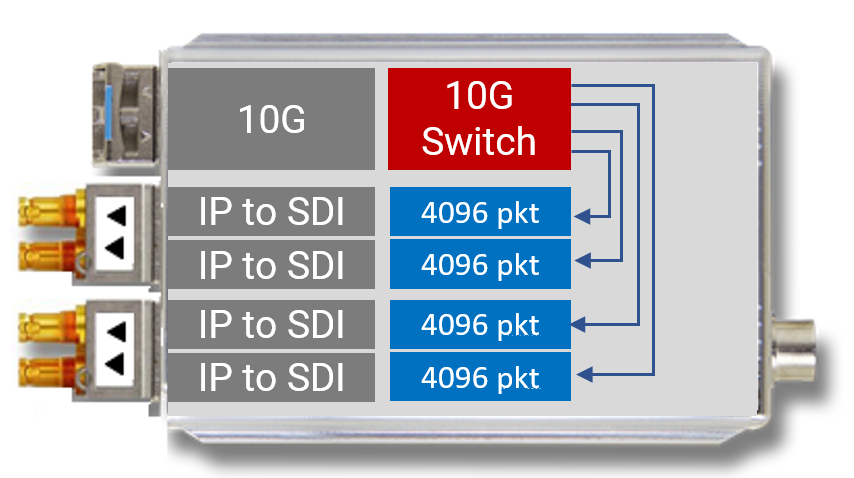
Figure 5. emVIEW-SDI-4 Details
2.0 TESTING METHODOLOGY
Ethernet and IP are widespread technologies that we can't imagine living without these days. The challenging factor of Ethernet and IP technologies is that they can sometimes be unpredictable. A network can deteriorate a flow by introducing packet delay, packet loss, out of sequence packets, duplication and errored packets. These issues are usually introduced by the buffering done by switches and routers. The other common problem is the network congestion that can cause delay or even packet drop. Additionally, packet reordering can be caused by multipath networks.
Engineers use different network impairment methods to emulate real world scenarios to test their system or devices. The goal is to validate that the system can work in any situation. These tools can introduce network delay or jitter. Jitter is the delay difference between packets, and, in real-time applications is a big concern. The introduction of jitter on a narrow sender signal will produce the same effect as if it was a wide sender ̶ in other words, it will make the flow bursty.
As video and media move to IP, these network impairment methods mentioned above will be useful for testing in production and post-production networks.
2.1 NETWORK DELAY AND IMPAIRMENT VALIDATION METHOD
Note: Embrionix does not claim this is the only way to validate the wide receiver in ST2110-21, but it is the method we used to validate wide receiver functionalities.
The following image shows the actual setup for the test. One or multiple senders is inserted in a top of rack switch. Instead of connecting the TOR switch directly to the core, we add the appliance that will help us introduce delay, jitter and all the other impairments we discussed previously. The core is then connected to the other TOR switch that hosts the de-encapsulators. The de-encapsulators will see the flows affected by the switches, but most importantly the impairment emulator. The SDI outputs are then connected to an analyzer to validate the output is valid throughout the tests (see Figure 6.).
The following image shows the actual setup for the test. One or multiple senders is inserted in a top of rack switch. Instead of connecting the TOR switch directly to the core, we add the appliance that will help us introduce delay, jitter and all the other impairments we discussed previously. The core is then connected to the other TOR switch that hosts the de-encapsulators. The de-encapsulators will see the flows affected by the switches, but most importantly the impairment emulator. The SDI outputs are then connected to an analyzer to validate the output is valid throughout the tests (see Figure 6.).
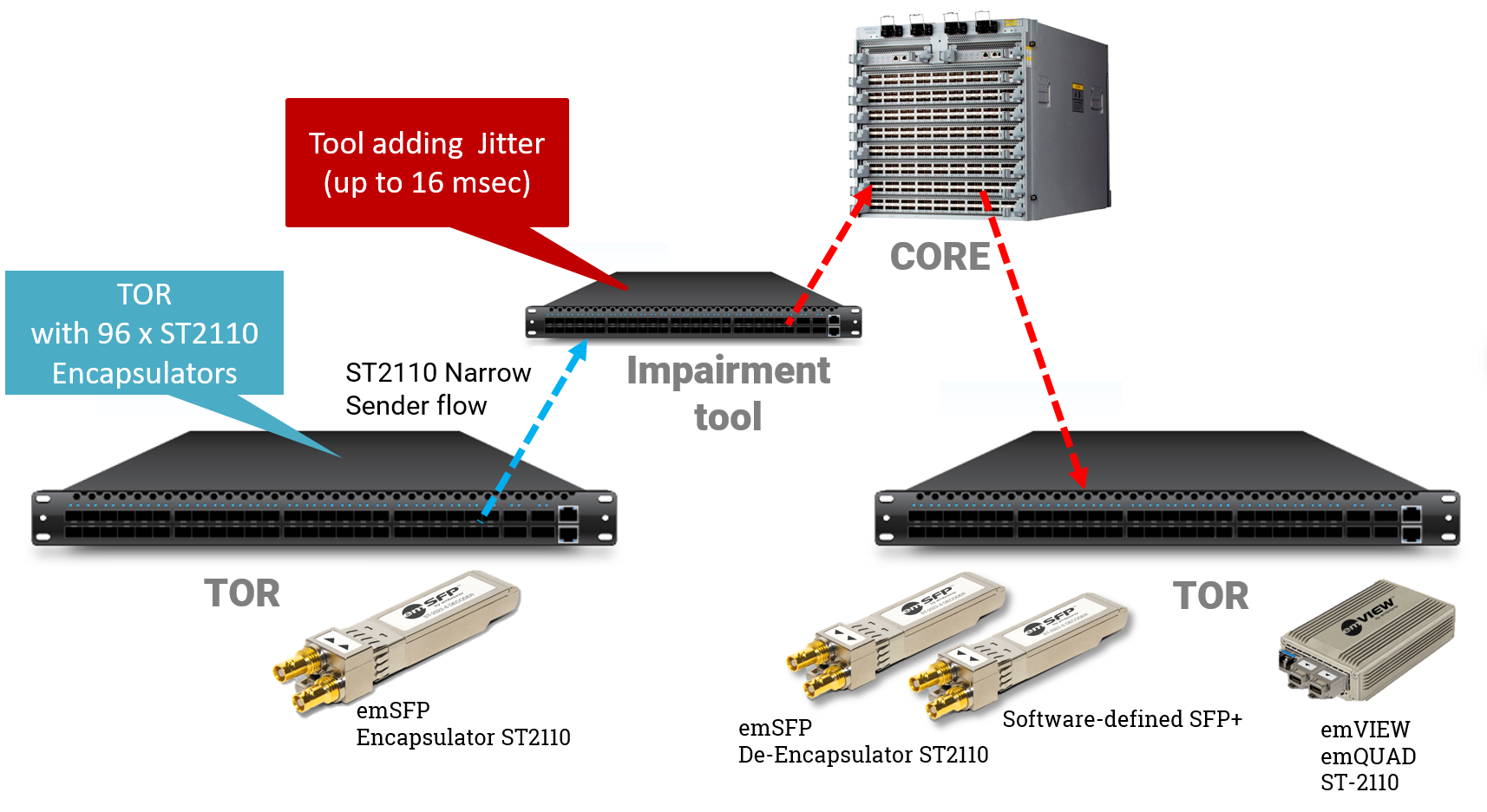
The impairment can be applied to a specific RTP flow or to all traffic. To apply to a certain flow, a rule is created based on parameters such as the VLAN or the destination IP. It can be useful to test the different essences separately and even more practical to validate the redundancy (ST2022-7). The Embrionix team did validate both the non-hitless path and the hitless path (ST2022-7).
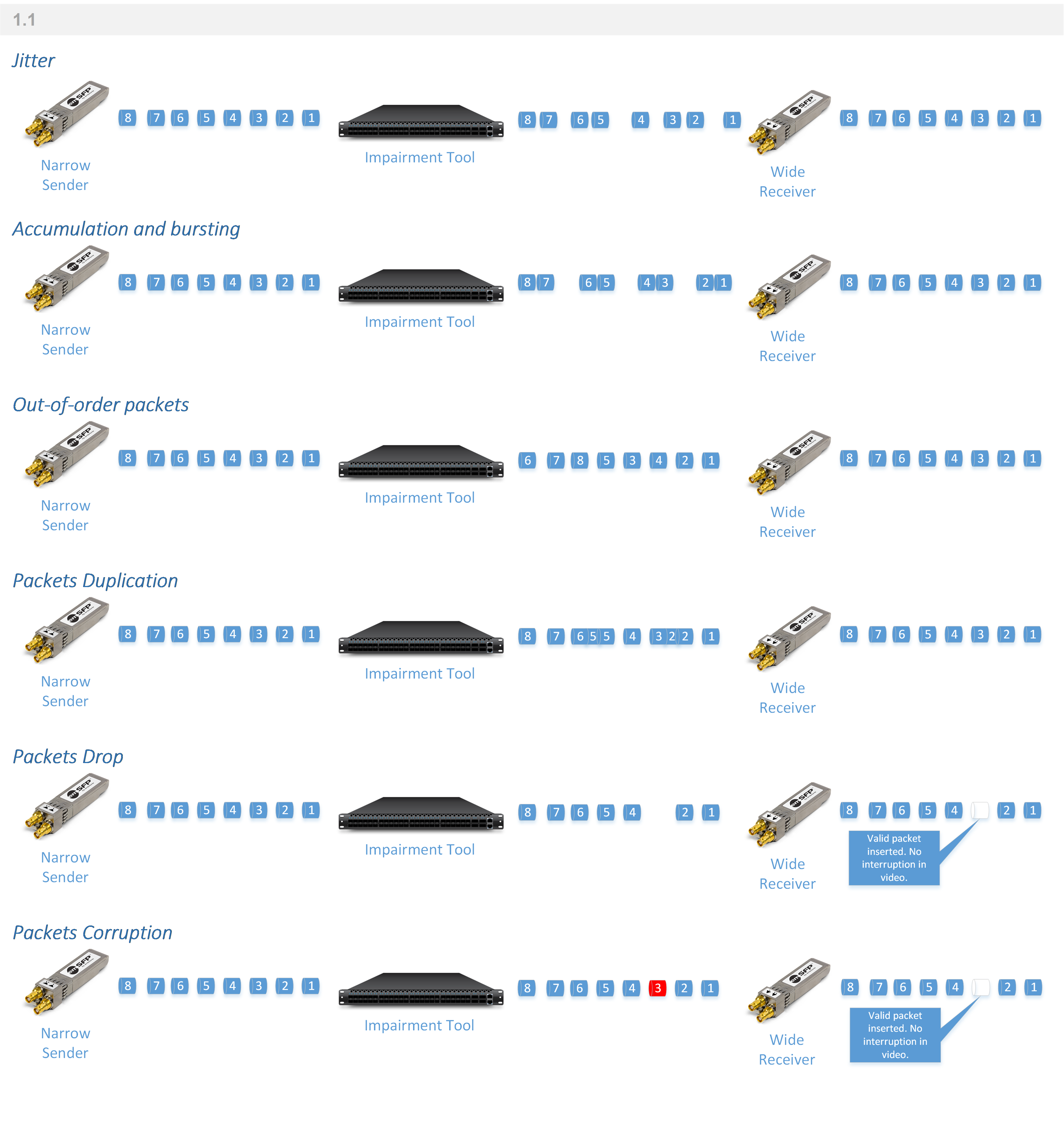
To test that the buffering works correctly on the de-encapsulator, one introduces a jitter from the minimum value accepted by the equipment to the configured buffer size of the device under test. Commonly the minimum is in the 10 microseconds range, but this differs from equipment to equipment. In our case, the tool allows us to do a very small jitter variation to a big one, to test accuracy.
Another test that can be executed is accumulating the packets in the impairment appliance buffers and then bursting them. This test will again test the buffer but instead of controlling the delay, one controls the number of frames directly. Using this method allows us to test both the buffer size as well as the capacity for the device to cope with a large burst.
Now that we have proven that the buffer is meeting the expected values, it can be tested to see if the device is able to handle out-of-order packets. To configure this, we usually configure how many packets we want to reorder in one sequence and how often. The number of packets needs to be selected based on the configured buffer of the receiver, just like the jitter test. It is also a good idea to validate that the device is able to handle the duplicate packets. This is configured the same way as the packet out-of-order test. The only difference here is that we need not to exceed medium bandwidth when duplicating packets.
A final test could be to validate that the receiver is rock solid ̶ and is a mix of all the above tests. One would need to adjust the value so as not to exceed the buffering capacity.
Once the tests that validate that the receiver conforms to the specification are complete, we can validate that the device can recover from outstanding scenarios. These tests validate that the receivers can recover successfully from buffer overflow or underflow as well as packet loss and corruption.
To test the buffer overflow, one can configure the tool to burst many packets ,which will exceed the buffer of the receiver. After the buffer is exceeded, we can remove the impairment and see if the receiver recovers correctly. Hereafter, it is possible to test the buffer underflow by configuring a long delay, letting the receivers starve for a while, then remove the delay and see that we recover.
Finally, we can validate that we are not largely affected by packet drop and errored packets. The objective of this test is to validate that the output continues to play without much impact on the user experience when we have some packet loss. Again, once the impairment is removed, the receivers should be back on their feet immediately. Note that the corrupted packets should be dropped by the switches and might not reach the device being tested at all. Depending on the type of decapsulator used, one might want to connect the output of the impairment tool directly to the device or at least as close as possible.
Embrionix products have been tested with all the above and successfully handled all the impairments.
2.2 DIFFERENT TYPES OF IMPAIRMENT
3.0 CONCLUSION
In conclusion, ST2110 receivers must be carefully designed to support wide sender (ST2110-21). Receivers must also be carefully tested to eliminate problems due to wide sender or any problems from network impacts (impairment or delay). Senders should also be carefully characterized to be narrow sender as much as possible in order to keep the buffer size to a minimum in a production environment.
Embrionix, the Embrionix logo and emSFP, emFUSION, emVIEW, emPROCESSOR, emMODULAR are trademarks of Embrionix Design Inc. All other products or services mentioned herein are the property of their respective owners. Copyright Embrionix Design Inc, 2009 -2018