All of us in the industry agree with all the good things that IP can bring to the table and broadcasters are getting ready to migrate from a traditional Base Band to IP based infrastructure, but not at any cost. It becomes important for them to understand how to efficiently build an optimized architecture that leverages the benefits that come with IP. It only makes sense to migrate to a new technology if it brings valuable advantages such as cost savings, additional functionality, and agile expendability. The cost of an IP infrastructure versus SDI can be radically higher if not designed properly. This white paper highlights several strategies to make the most out of your IP infrastructure. This document is describing architecture solutions in the context of uncompressed video distribution within a broadcast plan.
Engineers are facing important challenges when designing additional control rooms or a completely new television facility. They need to design an infrastructure that meets the short-term requirements while anticipating for possible expansion. The current design must be adapted for future expansion without needing major re-built engendering astronomical cost and it should be possible to invest slightly more now and quickly recover this investment later when additional equipment will be needed. IP infrastructures naturally provide expendability. This is one of the key motivation to migrate to this new technology. IP systems have been deployed in small and very large scales applications and used in many different markets. The technology is proven, cost- effective and scalable.
TV stations usually operate on a 24/7 basis. Therefore, it is mandatory to design a system that can resist any failure that could compromise the operation inside the station. An interruption of service can lead to important loss of revenues. It is mandatory to design a system that allows continuous operation as well as allowing equipment to be maintained and upgraded as needed. In addition, IP signals are slightly more delicate than SDI, therefore there is a need for a mechanism to protect the signals flowing in the network to maintain their integral quality.
Broadcast television media’s use quite a bit of bandwidth compared to other types of data such as file transfer. Although audio and metadata aren’t too data intensive, each uncompressed video signal consumes gigabits of space in the network. IP switches transporting these signals increase in cost as much as bandwidth is increased. Any waste of expensive ports on the network will impact your system cost.
Spine/Leaf architecture was introduced to create a fast, predictable, scalable, and efficient communication architecture in a data center environment. The Spine/Leaf architecture is configured in an Equal-Cost Multipathing (ECMP) allowing all connections to be utilized at the same time while remaining stable and avoiding loops within the network. This system can scale gracefully by adding Leaf and Spine switches to the network.
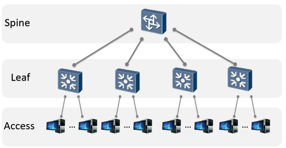
Figure 1: Spine Leaf architecture
With this topology, the Leaf switches are used to interconnect the devices providing and requiring data.These switches typically are equipped with lower bandwidth ports (1GE, 10GE, 25GE) and some higher bandwidth ports (40GE, 100GE) to aggregate to the Spine. The Spine switch is equipped with high bandwidth ports mainly.
The cost of the port is intimately related to the internal capacity of the switch to route all the signals at line rate. On a line rate switch, the internal bandwidth must be equal to the number of ports multiplied by their bandwidth. For example, a Spine 32x 40G port switch must handle 1,28Tbps switching capacity. A Leaf switch does not offer that same line rate capacity from the I/O ports to the aggregation. They are typically configured with a ratio of about 3:1 to save some cost on the hardware.
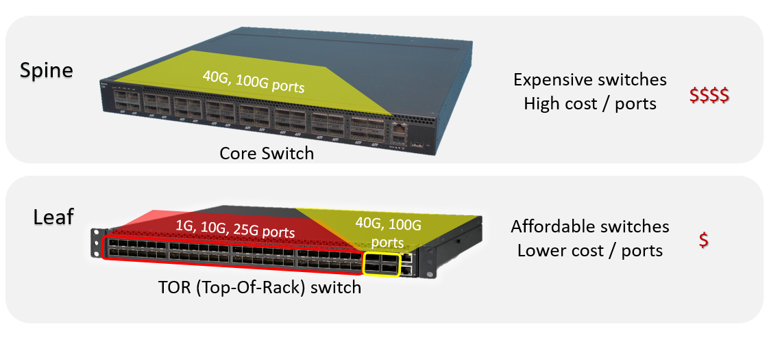
Figure 2: Spine switches versus Leaf switches
The ratio is determined by the practical possibilities of filling up each I/O ports of the switch and requirement of data to be uplinked to or downlinked from the Spine switch. At a peak demand, the impact of oversubscription is reasonably managed with retries and user impact is acceptable in most cases. This wise optimization allows significant cost reduction of the switch without compromising the operation.
For example, in Figure 3, a standard 48 x 10GE ports switch can typically provide four 40GE QSFP aggregation links for a total of 160Gbps of bandwidth corresponding to only 33% of the potential bandwidth from the I/O ports with 480Gbps. A minority of manufacturers propose better ratios at much higher price, but it defeats the purpose of using economical COTS (Commercial-Off-The-Shelf) equipment.
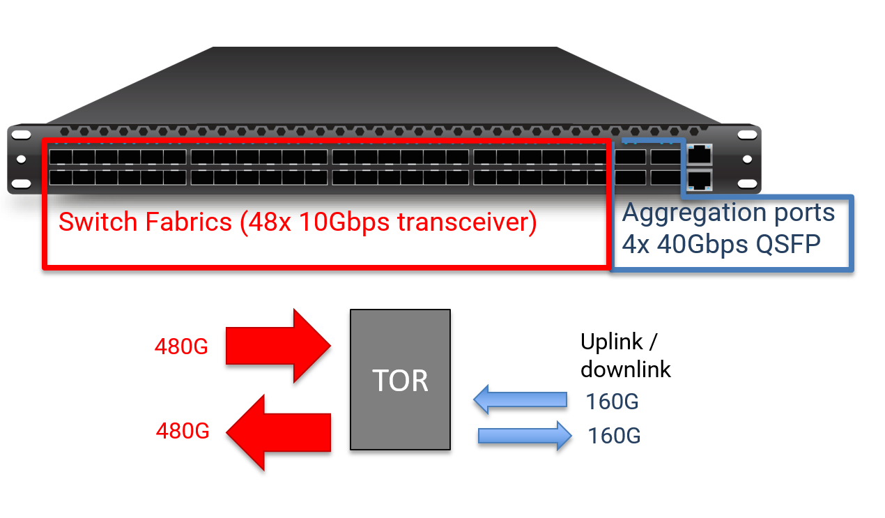
Figure 3: Typical TOR switch I/O versus aggregation bandwidth
A broadcast IP infrastructure is not used so differently, but some specific requirements expose limitations of COTS switches.
Additional network requirements must be considered to support uncompressed type flows containing a large amount of data. Uncompressed Audio/video data must be delivered in a predictable and deterministic manner, otherwise, the quality is greatly compromised. The system must be non-blocking and always provide enough bandwidth to bring the signals to any destination even at peak demand. Dropping packets is not acceptable as the impact is visually and audibly disruptive.
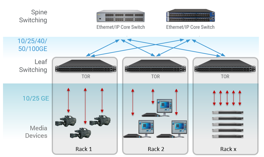
Figure 4: Use of Spine/Leaf inside a broadcast station
Following the Spine/Leaf approach, the equipment providing the data is connected to a TOR typically located inside the same rack. The TOR switch first makes the aggregation of data, then interconnect to Spine switches. This strategy greatly contributes to reducing the distance of fiber optical cables connecting to the IP network.
Inside the engine room of a TV station, the equipment is installed and positioned in their racks strategically for various maintenance reasons. Servers can be installed inside a set of rack located in the engine room, and multiviewers at a different location, the same approach applies for other types of equipment. SDI devices requiring to be integrated within the IP network might be grouped together so they can be connected to the gateway devices.
In large facilities, with centralized engine rooms, the distance between the equipment can be significant. A Spine/Leaf architecture helps to reduce the length and quantity of cables interconnecting to the IP network. Each equipment is connected locally with short fiber to a TOR switch. The TOR switch aggregates the many signals to interconnect to the Spine switch using fewer fiber strands. This provides a clear advantage over any other centralized switching methodologies.
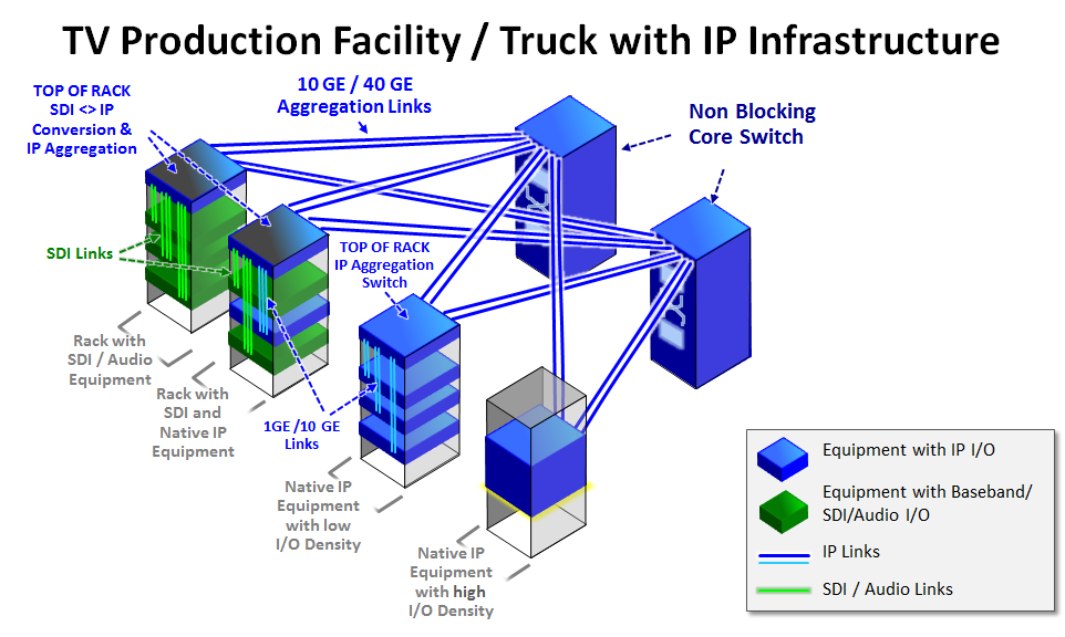
Figure 5: Typical IP Production Infrastructure
In a typical Broadcast production plan, each equipment provides few inputs and outputs, mostly in an uneven input and output balance. The I/O configuration may vary from one device to another, but rarely you will find a device using the full 10G bandwidth of the physical connection.
In Figure 6, typical sources such as cameras and servers providing an input and receiving an output through the 10GE port. With 1.5G video, this represents only 15% of usage of the port therefore 85% of the capacity is not being used.
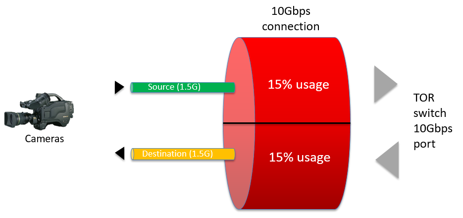
Figure 6: Typical IP equipment using only 15% of a 10GE I/O port
In Figure 7, a different set of equipment receiving more signals but sending fewer signals through the 10GE port. In this case, the port is better utilized although it is still not using the full 10G bandwidth in both directions.
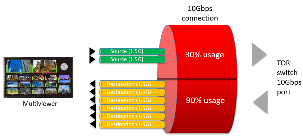
Figure 7: Other equipment using the most of only one direction of the 10GE I/O ports
This estimation of cost comparison, calculating the usage of bandwidth in a typical television stations including a large studio, the playout area, and the incoming feed area. A realistic set of equipment is included to give an accurate sense of how to properly deploy such a system. It is observed that very few broadcast devices, about 10%, use more than 50% of the bandwidth of a 10GE port. On the other hand, each port of the Spine switch is well utilized in at least one direction. With this efficient aggregation, this system only requires 40 ports of the Spine switch, whereas nine aggregation switches provide interconnection to 372 devices.
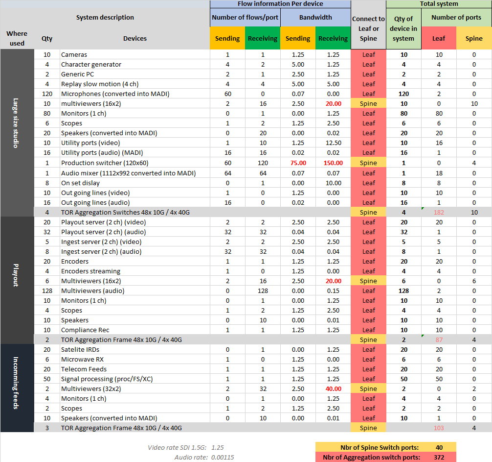
Table 1: Typical TV station Case study showing bandwidth utilization
Based on average industry pricing, Spine (40GE port Spines) are 7 times more expensive per port than TOR (10GE leaf) switches. A judicious use of an aggregator switches for some devices and direct connection to Spine with other devices can lead to important cost saving.
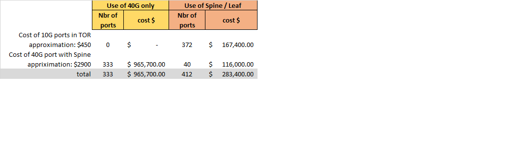
Table 2: Estimation of cost of an IP switches (cost varies between vendors
Unlike other vendors, the Embrionix solution does not require additional gateway equipment consuming additional rack space to convert SDI to IP. This contributes to the substantial cost, space, and power consumption savings.
Additionally, the quantity of fiber optic cables and modules is reduced by half.
Embrionix’s emSFPs blend into the existing IP infrastructure to properly adapt SDI signals or IP native into the network. emSFP-Gateway modules are installed inside the TOR switches to convert the signals from SDI to IP and vice versa. This same TOR switch is already present to accommodate other IP native equipment.
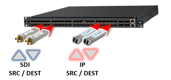
Figure 8: SDI or IP equipment connect to the same TOR
Unlike other vendors, the Embrionix solution does not require additional gateway equipment consuming additional rack space to convert SDI to IP. This contributes to the substantial cost, space, and power consumption savings.
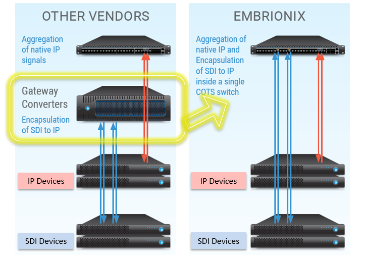
Figure 9: emSFPs naturally integrate SDI inside your IP Network
Additionally, the quantity of fiber optic cables and modules is reduced by half.
Another benefit of the solution is the ease of migration from SDI to IP. As your devices gradually become IP ready, you simply need to replace the SFP inside the switch connecting to your device. No need for a major re-build of the rack, each emSFP provides a modularity of one or two channels at a time.
As explained previously in this document, an aggregation switch does not provide a 1:1 ratio from the I/O ports to the aggregation ports. This means there are no reasons to try to fill up each 10GE port with media in hope to optimize your system. The capacity to aggregate the data to the Spine is your bottleneck, therefore, the total bandwidth at the I/O ports cannot be fully utilized.
Embrionix’s SFP can convert two signals per 10GE port. You cannot further optimize the density to a smaller footprint as you are limited to the physical space required for the two mini-BNC allowing to connection to the external device.
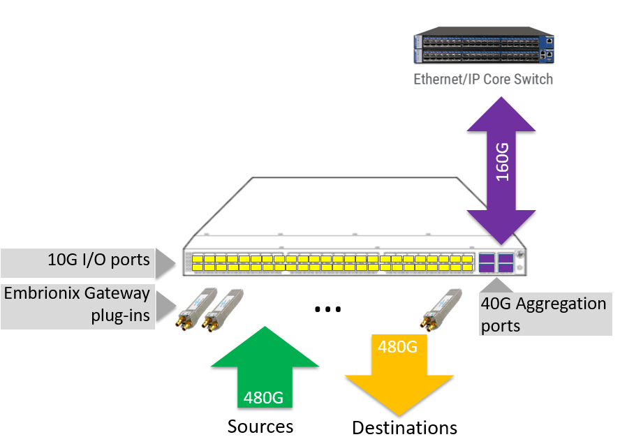
Figure 10: I/O versus aggregation bandwidth capacity
In table 3, are listed the different scenarios describing I/O port usage and the capacity to aggregate all signals to the Spine switch. The example is based on the use of a standard COTS Leaf switch of 48x 10GE ports with 4x 40GE ports. The first scenario is theoretical and shows the full use of every 10GE ports. In this condition, only 16 ports can be used before maximizing the 160GE limit of the aggregation ports. When configured with two 3G signals per port, 26 ports for a total of 52 channels can be used. Two 1.5G channels per port allow the use of all 48 ports for a capacity of 96 channels. This is the maximum of signals that can be conceivably treated and flowing inside a single RU of space.
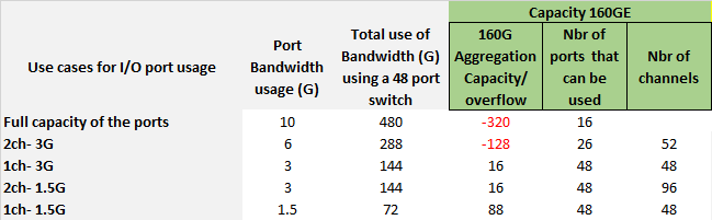
Table 3: Aggregation use cases calculation
It is obvious that a Spine / Leaf architecture with the judicious use of aggregation is needed to efficiently interconnect devices into an IP network. The optimal use of bandwidth inside each switch will contribute in making the solution a lot more cost effective. Cable management is simplified also due to the proximity of the TOR switch and the media devices. Embrionix’s emSFP opportunistically integrate within existing TOR switches contributing to even more savings. 96 (SDI to IP) gateway conversions can be treated inside a single rack space forming an unbeatable proposition. Most importantly, the Spine / Leaf architecture can naturally expand. A minimal initial investment in this direction can allow future cost saving to your next system expansion.
Typical redundant architectures use two separate core networks. The redundancy is useful to protect the signals flowing inside the network against potential interruption of the network.
The first network interruption to prevent is the failure of the Spine switch. Any failure of this device will engender loss of connectivity to a high number of devices if not all. To make a parallel with an SDI plan, losing the Spine switch has an equivalent impact to losing the core router of a TV station. An SDI routing infrastructure prevents this risk by using two routers and devices connecting to both routers using DAs and Changeover at the Destination. This architecture is effective and necessary when maintenance is required on a router. A seamless failover from Primary to Secondary allows maintenance to be achieved on one of the two routers.
The second necessity for adding redundancy to an IP infrastructure is to prevent any packet loss to impact the flows at the receiving devices. Some studies have determined that losses of packets inside an IP infrastructure are more frequent and more harmful than losses of SDI bits inside an SDI plan. Therefore, a strategy to protect the data on a packet by packet basis is important.
A methodology called Hitless Redundancy has been invented to resolve this issue. It consists of creating duplicate flows of the Sender inside two independent networks so that the Receiver can compare them and select the best one available at any given time. The solution operates in real time and on a per packet by packet basis. The receiver must have some buffering capabilities to lock the two feeds together and compare the equivalent set of packets and furthermore guaranty a seamless switching method (Hitless).

Figure 11: Hitless switching overview
Redundancy implementation involves additional cost. You can choose to build a system that will resist all possible failures, but will it be cost effective? All this redundancy will add more equipment, more power, and more maintenance. Over-designing your redundancy will have a major impact on your system cost.
The redundancy protection starts at the Spine. As explained in section 3.0, the failure of these switches can cause a major impact to the operation. The Leaf switches are not necessarily included in the Hitless Redundancy strategy. The failure of a Leaf can only impact a small subset of devices. This approach can be compared with other bulk processing devices that provide multiple processing functions inside the same frame. The system can be architected to distribute principal feeds in different Leaf switches to minimize the impact of a failure. Maintenance and upgrades of the TOR will only impact this small subset of the system.
A practical and economical approach to building a robust system with redundancy at the Spine consists of using a single Leaf switch connected to the devices. In this case, the switch must provide an internal mechanism to properly identify the flows and direct them to the Primary and Secondary Spines. This is possible using existing IT tagging methodologies. This way, the signals entering the switch are duplicated and a version of a flow is sent to the Primary switch and its companion version is sent to the Secondary switch. At the receiving end, the device joins the Primary and Secondary feeds coming from the Spines and perform the Hitless redundancy. This implementation uses half of the TOR switches while not compromising on hitless redundancy.
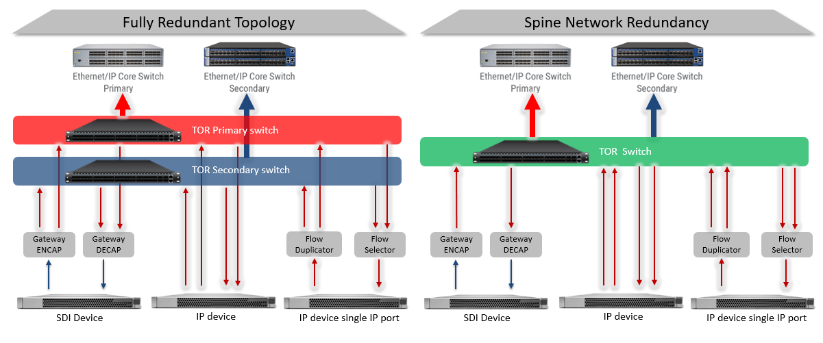
Figure 12: Practical Spine Network Redundancy
Embrionix solution does not use additional rack space since the signal adaptation modules are installed directly inside the TOR switches. The TOR switch becomes a bulk gateway adaptor for any type of devices whether they have native IP, redundant IP or SDI ports.
Each SFP can treat two signals per 10GE port. Gateway SFP will encapsulate or decapsulate the IP signals at the host of the connector inside the switch and deliver SDI on the other side to connect to the devices. IP to IP SFPs can simply receive one IP signal and generate a companion flow allowing both Primary and Secondary flows to reach their respective Spines.
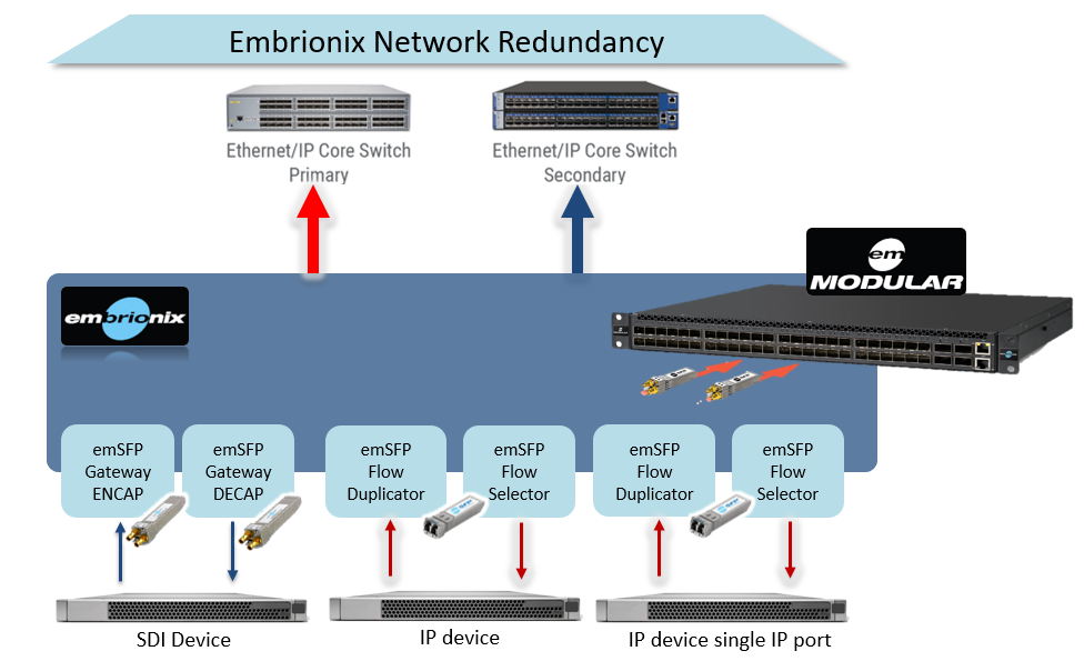
Figure 13: All integrated and economical redundancy
emMODULAR is a broadcast specific TOR aggregator. The hardware is still a generic IT type appliance but configured with an Embrionix software managing the traffic flow and supporting Spine redundancy. The emMODULAR is configured to keep both networks totally isolated and does not create any unattended routes between the Spines.
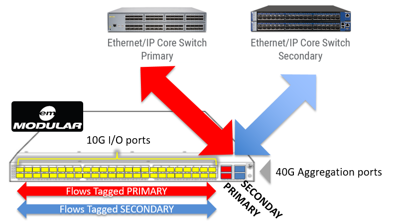
Figure 14: Flow Tagging for Spine Redundancy support
As mentioned in the aggregation calculation considering the redundancy requirement, it is understood that each flow must be doubled with its companion flow, and this creates an impact on the switch capacity.
The aggregation must be split in two to bring flows to both Spines which leaves only 80G of data per 1RU aggregation switch.
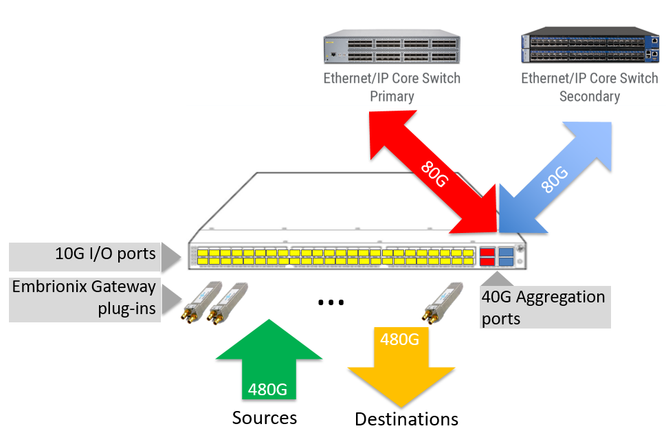
Figure 15: Aggregation considering redundancy
In which case, fewer ports can be used. This is a totally acceptable compromise as the density is still much higher than any other solutions and your failure block is maintained in a reasonable quantity of channels.
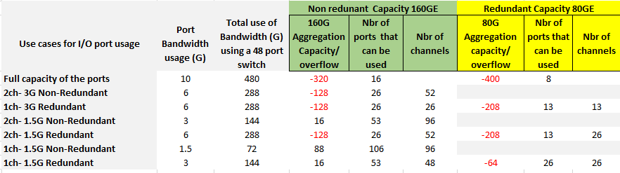
Table 4: Aggregation calculation in a Redundant system
Designing a redundant architecture is a necessity, especially for large TV stations sharing signals across multiple operation areas. Applying the redundancy where it is essential and wise compromises when there is no added value is an opportunity for space and cost savings. Embrionix integrates the signal adaptation right inside the TOR switch while also managing the hitless redundancy for IP native or SDI signals. In comparison with other competitive solution, Embrionix’s emSFPs and emMODULAR solution uses a fraction of the space and reduces your cost of ownership with less equipment without sacrificing robustness.
In this paper, important topics have been covered helping you design a cost-effective IP infrastructure. The cost of the system is not only based on initial cost when purchasing the equipment, but also materializes into derived costs such as rack space, cost of power, and the cost of ownership maintaining the equipment.
Make sure your network is properly engineered with proper aggregation to optimize the use of your Spine ports. The Spine / Leaf architecture enables scalability of your system without the necessity of up-front investments.
TOR switches are inherently required to interconnect native IP devices. emSFP “Plug-ins” can adapt any SDI or IP devices right inside these COTS switches. Therefore, IP and SDI equipment can coexist inside the same equipment rack concentrating into the same TOR switch. Embrionix offers a modular platform used for I/O connectivity including up to 96 gateway conversions inside a single RU while also offering other advanced processing and conversion features within the same form factor.
Hitless redundancy can be supported at a reasonable cost using Spine redundancy and optimized aggregation. Embrionix supports hitless redundancy whether the device is equipped with SDI ports or IP ports. Smart emSFPs can be used in line with your IP devices or as a resource inside the TOR switch allowing flows from devices lacking hitless redundancy to be supported. emMODULAR simplifies your system design by handling the redundant traffic flowing to the Spines.
In this transition to IP, Embrionix enables all the benefits of IP while making no compromises on your important requirements. The solution blends into your network leaving space and more of your budget available for other core equipment.
Embrionix, the Embrionix logo and emSFP, emFUSION, emVIEW are trademarks of Embrionix Design Inc. All other products or services mentioned herein are the property of their respective owners. Copyright Embrionix Design Inc, 2009 -2016