The SFP (small form-factor pluggable) was created to be used in Informational Technology applications such as telecommunication and data communication. The form-factor and the electrical interface (host board interface) are specified by a multi-source agreement referred as SFP-MSA. The early SFPs were created to be transceiver modules, meaning one receiver port (optical receiver, also known as ROSA) and one transmitter port (optical laser, also known as TOSA). These SFPs were not designed to support the SDI video signal, their performance with video signal were bad and the resulting bit error rate high.
NOTE: A more recent version of SFP MSA Transceiver multi-source agreement now exist. It has been renamed SFF-8071 and is managed by the SNIA.
Generally speaking, Embrionix Video SFP (emSFP) is fully compliant with video SFP design and SFP/SFP+ cages. The basic difference is on the power rating of the emSFP, the advanced processing built inside the emSFP and the different bit rates supported by the emSFP, from DC up to 12G-SDI.
NOTE: Because emSFP have more processing power, the overall emSFP power requirement is higher than standard SFPs (1 watt) and in the same range of SFP+ (1.5 watts).
The host board interface of an SFP port comprises of 2 main parts: the cage which ensures that the SFP, video SFP, SFP+ and the emSFP is held in place and the board connector that gets the signals to and from the SFP. Engineers starting new designs should take special care with the selection of the SFP and SFP+ cages and connectors.
The SFP and SFP+ cages are composed of the metal body and the host connector. More specifically, the metal body have the EMI pins used to connect it to the final enclosure, the pins to be soldered or press fit in the PCB and finally for the SFP, the retainer (a small latch at the bottom of the metal enclosure).

The retainer (latch) should be carefully studied when choosing the SFP cage or SFP+ cages. This retainer is important to ensure the SFP, video SFP or emSFP stays in place when insertion is performed. Embrionix recommends using soldered cages to support the weight of coaxial cables & video SFP and other types of cables.
Importance should be taken when choosing a video SFP. Case and point: the retaining mechanism (the triangle shown in the previous image) is an important part of the design that prevents movement inside the cage. A poor SFP mechanical design may create problems such as poor signal connections and a high Bit Error Rate, insertion and extraction problems or even permanent SFP or product damage. As such, the retaining mechanism from the SFP-MSA specification should be correctly implemented to ensure adequate retention.
SFP+ cages can be sourced with a heatsink fitted on top of the cage to ensure the support of the SFP+ supplemental power requirement. These SFP+ cages can be used when a minimal airflow is present in the system. Basically, when the SFP+, video SFP or emSFP are inserted in the cage, a latch over the SFP+ is actuated and the heatsink firmly sits on top of the SFP ensuring optimal thermal conductivity.

Care should be taken when selecting video SFP suppliers. The SFP housing should have an angle, a bevel, at the back to correctly mate with SFP+ cages. This bevel ensures the heatsink latch mechanism isn’t blocking when inserting the video SFP or emSFP. Embrionix video SFP are designed to ensure compatibility with the SFP cages and SFP+ cages from various manufacturers.
NOTE: The Embrionix team can help your engineers with the correct selection of the SFP or SFP+ cages.
The SFP and SFP+ host connector can look the same, but critical differences exist. . The SFP+ host connector has been optimized for signals over 10Gbps and the SFP host connector has been specified for 5Gbps or lower. Embrionix recommends using SFP+ host connector with video SFP and emSFP for 6G-SDI and 12G-SDI.

The SFP host connectors are specified to hold up to 100 insertions and extractions. The insertions affects the plating on the pins. To improve this, manufacturers supplied SFP host connectors with higher amount of gold platting on the pins. Some SFP host connectors are specified for 1000 insertions and extractions. This type of connector will hold up to standard usage of video SFPs and emSFPs in a product.
NOTE: Such attention to details should be taken early on when designing the system.
The SFP+ host connector is optimized for high-speed differential signals. The SFF-8431 specification includes measurements to ensure the compatibility between the host board (product) and the SFP+ modules.
NOTE: For more information about the measurements methods and resulting values, please consult the SFF-8431 specification, Appendix D Test Methodology and Measurement (Normative).
Because video SFPs are inspired by MSA SFPs (data communication and telecommunication ones), it makes sense to start with understanding the original MSA SFP technical challenges. In the design rules, we will explore the ports on SFPs, data input pair, data output pair, I2C communication link and power. The following table as well as other information contained in this section comes from MSA SFP Specification . MSA SFP Specification page 21 shows the pins definition and their mating order.
NOTE: The SFP, SFP+ and video SFP / emSFP are designed in a way that the ground connections will be made first, followed by the VCC and then the other signals.
Table 1. Pin Function Definitions

TX Fault is an open collector/drain output, which should be pulled up with a 4.7k – 10kΩ resistor on the host board. Pull up voltage shall be set between 2.0V and VccT, R+0.3V. When high, output indicates a laser fault of some kind. Low indicates normal operation. In the low state, the output will be pulled to less than 0.8V.
NOTE: No peculiar routing rule is needed for the TX Fault signal.
TX disable is an input that is used to shut down the transmitter optical output. It is pulled up within the module with a 4.7 – 10kΩ resistor. Its states are defined as such: low (0 – 0.8V) for “Transmitter On”, high (2.0 – 3.465V) or floating for “Transmitter Disabled”.
NOTE: No peculiar routing rule is needed for the TX disable signal.
These are the module definition pins. They should be pulled up with a 4.7k – 10kΩ resistor on the host board. The pull up voltage shall be VccT or VccR. Mod-Def 0 is grounded by the module to show the host module is presence. MOD-DEF_1 is the clock line and MOD-DEF_2 is the data line of the two-wire serial interface.
Care should be taken when routing the I2C bus. Capacitance should be minimized and limited to 400pF (per I2C specification) and only one SFP shall be directly connected to the I2C bus controller. Otherwise, contention will append since SFPs all have common I2C physical bus addresses. Physical address A0h contains the EEPROM and A2h contains the warnings and alarms. If multiple SFPs needs to be controlled by a single I2C bus controller, an I2C Switch or Address Translator could be used on the host board to avoid bus contention.
NOTE: Embrionix EB35TD1R-SM and EB35TD1T-SM features internal 4.7kΩ pull ups to a power rail derived from the combined VccT and VccR pins.
This is an optional input used to control the receiver bandwidth for compatibility with multiple data rates (most likely Fiber Channel 1x and 2x Rates). When implemented, the input will be internally pulled down with > 30kΩ resistor. The input states are defined as such: low (0 – 0.8V) for “Reduced Bandwidth”, high (2.0 – 3.465V) for “Full Bandwidth” and open for “Reduced Bandwidth”.
NOTE: No peculiar routing rule is needed for the Rate Select signal.
LOS (Loss of Signal) is an open collector/drain output, which should be pulled up with a 4.7k – 10kΩ resistor. Pull up voltage shall be set between 2.0V and VccT, R+0.3V. When high, this output indicates that the received optical power is below the worst-case receiver sensitivity. Low indicates normal operation. In the low state, the output will be pulled to less than 0.8V.
NOTE: No peculiar routing rule is needed for the LOS signal.
RD-/+: These are the differential receiver outputs. They are AC coupled 100 Ω differential lines which should be terminated differentially with 100 Ω at the user receiving circuit. Since the AC coupling is done inside the module, it is not required to implement additional AC coupling on the host board. The voltage swing on these lines will yield between 370 and 2000 mV in differential mode (or 185 – 1000 mV per single ended leg) when properly terminated.
TD-/+: These are the differential transmitter inputs. They are AC coupled differential lines featuring a 100Ω differential termination inside the module. Since the AC coupling is done inside the module, it is not required to implement additional terminations on the host board. The inputs will accept differential swings of 500 – 2400 mV in differential mode (or 250 – 1200 mV per single ended leg). However, it is recommended that values between 500 and 1200 mV in differential mode (or 250 – 600 mV per single ended leg) be used for optimal EMI performance.
Video data content differs from Informational Technology data content. One fundamental difference is that video is transported in a unidirectional way. Informational Technology SFPs must transport data in both directions to establish a link. With video SFPs or emSFPs, a link can be established through one simplex fiber optic or coaxial cable transporting video data. This reason has been the main driver to create different pinouts for the video SFP.
The following table shows the difference of the direction of the signals. The full reference document is available on the Embrionix website.
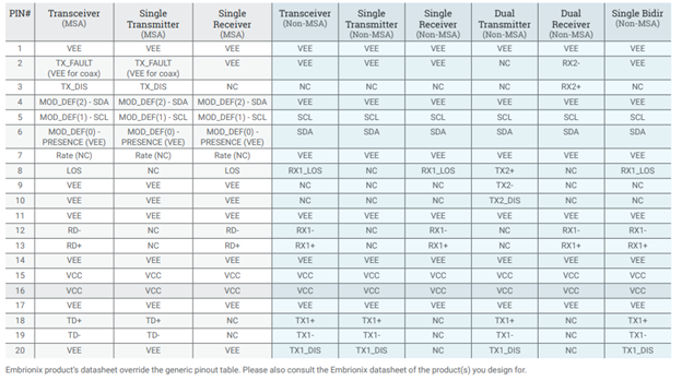
TX disable is present on transceiver video SFPs, single transmitter video SFPs and two separate TX disable are present on dual Transmitter video SFP.
TX disable is an input that is used to shut down the transmitter optical output. It is pulled up within the module with a 4.7 – 10kΩ resistor. Its states are low (0 – 0.8V) for “Transmitter On”, high (2.0 – 3.465V) or floating for “Transmitter Disabled”.
NOTE: No peculiar routing rule is needed for the TX disable signal(s).
These signals should be pulled up with a 4.7k – 10kΩ resistor on the host board. The pull up voltage shall be VccT or VccR. SCL is the clock line and SDA is the data line of two-wire serial interface.
Care should be taken when routing the I2C bus. Capacitance should be minimized and limited to 400pF (per I2C specification) and only one SFP shall directly be connected to the I2C bus controller. Otherwise, contention will append since SFPs all have common I2C physical bus addresses. Physical address A0h contains the EEPROM and A2sh contains the warnings and alarms. If multiple SFPs needs to be controlled by a single I2C bus controller, an I2C Switch or Address Translator could be used on the host board to avoid bus contention.
Please note that the MOD_DEF2 and MOD_DEF0 pins from MSA SFP specification take other roles and names with Non-MSA Video SFPs or emSFPs variants.
NOTE: Embrionix EB35TD1R-SN and EB35TD1T-SN features internal 4.7kΩ pull ups to a power rail derived from the combined VccT and VccR pins.
The “Rate Select” feature from the SFP specification is not implemented in Video SFPs.
LOS is present on transceiver video SFP and single receiver video SFP.
LOS (Loss of Signal) is an open collector/drain output, which should be pulled up with a 4.7k – 10kΩ resistor. Pull up voltage shall be set between 2.0V and VccT, R+0.3V. When high, this output indicates that the received optical power is below the worst-case receiver sensitivity (as defined by the standard in use). Low indicates normal operation. In the low state, the output will be pulled to less than 0.8V.
NOTE: No peculiar routing rule is needed for the LOS signal.
1 RX pair is present on Transceiver video SFP and single receiver video SFP. 2 RX pairs are present on dual receivers.
RX-/+: These are the differential receiver outputs. They are AC coupled 100 Ω differential lines which should be terminated differentially with 100 Ω at the user receiving circuit. Since the AC coupling is done inside the module, it is and is thus not required to implement additional AC coupling on the host board. The voltage swing on these lines will yield between 370 and 2000 mV in differential mode (or 185 – 1000 mV per single ended leg) when properly terminated.
1 TX pair is present on transceiver video SFP and single transmitter video SFP. 2 TX pairs are present on dual transmitters.
TX-/+: These are the differential transmitter inputs. They are AC-coupled, differential lines featuring a 100Ω differential termination inside the module. Since the AC coupling is done inside the module, it is not required to implement additional terminations on the host board. The inputs will accept differential swings of 500 – 2400 mV (250 – 1200 mV single-ended). However, it is recommended that values between 500 and 1200 mV in differential mode (or 250 – 600 mV per single ended leg) be used for optimal EMI performance.
--
FOR MORE INFORMATION: Please contact Embrionix sales team to get more information about the emSFP. Embrionix_Sales@riedel.net.
###
About Embrionix
Embrionix, a subsidiary of Riedel Communications, designs and builds innovative, advanced SMPTE video SFPs to close the gap between fiber optic deployments, coaxial deployments, legacy composite deployments, and emerging technologies, such SDI to IP SFPs. By leveraging its core competencies in video broadcast, the company OEMs highly flexible SFP modules (emSFP) to major manufacturers in the industry. Embrionix headquarters are based in Laval, Quebec. Embrionix sales offices, representatives, and distribution offices are located in Canada, United States, United Kingdom, Germany, France, and Japan.
About Riedel Communications
Riedel Communications designs, manufactures, and distributes pioneering real-time video, audio, data, and communications networks for broadcast, pro audio, event, sports, theater, and security applications. The company also provides rental services for radio and intercom systems, event IT solutions, fiber backbones, and wireless signal transmission systems that scale easily for events of any size, anywhere in the world. Riedel is headquartered in Wuppertal, Germany, and employs over 700 people in 25 locations throughout Europe, Australia, Asia, and the Americas.
All trademarks appearing herein are the property of their respective owners.